


Interfacing 8051 with Stepper Motor – Introduction:
A stepper motor is a device that translates electrical pulses into mechanical movement in steps of fixed step angle. The stepper motor rotates in steps in response to the applied signals. It is mainly used for position control. Let’s see in detail about Interfacing 8051 with Stepper Motor.
Structure of Stepper motor:

- Stepper motors have a permanent magnet called rotor (also called the shaft) surrounded by a stator. The most common stepper motors have four stator windings that are paired with a center-tap.
- This type of stepper motor is commonly referred to as a four-phase or unipolar stepper motor.
- The center tap allows a change of current direction in each of two coils when a winding is grounded, thereby resulting in a polarity change of the stator.
Interfacing 8051 with Stepper Motor
- Even for Interfacing 8051 with Stepper Motor of small size it require a current of 400 mA for its operation. But the ports of the microcontroller cannot source this much amount of current.
- If such a motor is directly connected to the microprocessor/microcontroller ports, the motor may draw large current from the ports and also damage it.
- So a suitable driver circuit is used with the microprocessor/microcontroller to operate the motor.
Schematic Diagram – Interfacing 8051 with Stepper Motor
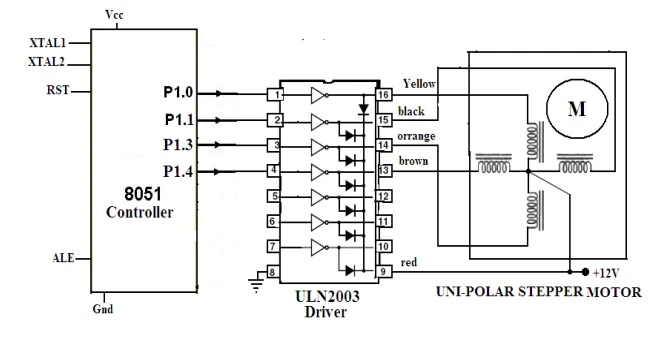
Motor Driver Circuit
- Stepper motor driver circuits are available readily in the form of ICs. ULN2003 is one such driver IC which is a High-Voltage High-Current Darlington transistor array and also can give a current of 500mA.
- This current is sufficient to drive a small stepper motor. Internally, it has protection diodes used to protect the motor from damage due to back emf and large eddy currents.
- So, this ULN2003 is used as a driver to interface the stepper motor to the microcontroller.
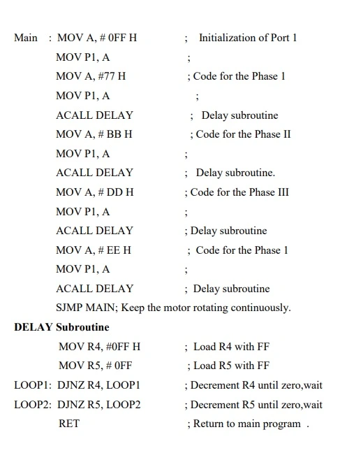
Assembly language program for Interfacing 8051 with Stepper Motor
Operation of 8051 Interface with Stepper Motor
- The important parameter of a stepper motor is the step angle. It is the minimum angle through which the motor rotates in response to each excitation pulse.
- In a four phase motor if there are 200 steps in one complete rotation then then the step angle is 360/200 = 1.8 Deg Angle . So to rotate the stepper motor we have to apply the excitation pulse.
- For this the controller should send a hexa decimal code through one of its ports. The hex code mainly depends on the construction of the stepper motor.
- So, all the stepper motors do not have the same Hex code for their rotation. (refer the operation manual supplied by the manufacturer.) For example, let us consider the hex code for a stepper motor to rotate in clockwise direction is 77H , BBH , DDH and EEH.
- This hex code will be applied to the input terminals of the driver through the assembly language program. To rotate the stepper motor in anti-clockwise direction the same code is applied in the reverse order. This is the operation of 8051 Interface with Stepper Motor.
LIKE WHAT YOU’RE READING?
CHECK OUT SOME OF OUR OTHER GREAT CONTENT HERE:
- ADVANTAGES OF STEPPER MOTOR
- WHAT IS A UNIVERSAL MOTOR ?
- WORKING PRINCIPLE OF SYNCHRONOUS MOTOR
- INDUCTION MOTOR: WORKING PRINCIPLE, TYPES & APPLICATION
- HOW ELECTRICAL MOTOR WORKS? – EXPLAINED


1 Comment