
Introduction: Power Factor Improvement Method
The cosine of angle between voltage and current in an a.c. circuit is known as power factor.The improvement of power factor is very important for both consumers and also generating stations. In this article let’s see various Power Factor Improvement Method.
Power Factor

In an a.c. circuit, there is generally a phase difference φ between voltage and current. The term cos φ is called the power factor of the circuit.
Power Factor Formula
Power factor = cos φ = cosine of angle between V and I.
where ɸ is the phase difference between the voltage and current phasor.
Unit For Power Factor
Since power factor is the ratio of active power and apparent power, it has no unit. That said, it is the quantitative measure of how much effective power is being used, without a unit.
Why Power Factor Correction is required?

- Most of the loads (e.g. induction motors, arc lamps) are inductive in nature and hence have low lagging power factor.
- The low power factor is highly undesirable as it causes an increase in current, resulting in additional losses of active power in all the elements of power system from power station generator down to the utilization devices.
- In order to ensure most favorable conditions for a supply system from engineering and also economic standpoint, it is important to have power factor as close to unity as possible.
Disadvantage of Low Power Factor
The power factor plays an importance role in a.c. circuits since power consumed depends upon this factor
Large kVA rating of equipment:
- The electrical machinery (e.g., alternators, transformers, switchgear) is always rated in *kVA.
- kVA= 𝑘𝑊/cos 𝜑
- It is clear that kVA rating of the equipment is inversely proportional to power factor. The smaller the power factor, the larger is the kVA rating. Therefore, at low power factor, the kVA rating of the equipment has to be made more, making the equipment larger and also expensive. i.e Cosφ α 1 kVA
Greater conductor size:
- To transmit or distribute a fixed amount of power at constant voltage, the conductor will have to carry more current at low power factor.
- This necessitates large conductor size Large copper losses. The large current at low power factor causes more I2R losses in all the elements of the supply system. This results in poor efficiency.
Poor voltage regulation:
- The large current at low lagging power factor causes greater voltage drops in alternators, transformers, transmission lines and also distributors.
- This results in the decreased voltage available at the supply end, thus impairing the performance of utilization devices. In order to keep the receiving end voltage within permissible limits, extra equipment (i.e., voltage regulators) is required.
Reduced handling capacity of system.
The lagging power factor reduces the handling capacity of all the elements of the system. It is because the reactive component of current prevents the full utilizations of installed capacity
Causes of Low Power Factor
Low power factor is undesirable from economic point of view. Normally, the power factor of the whole load on the supply system in lower than 0·8. The following are the causes of low power factor:
- Most of the a.c. motors are of induction type (1φ and 3φ induction motors) which have low lagging power factor. These motors work at a power factor which is extremely small on light load (0·2 to 0·3) and also rises to 0·8 or 0·9 at full load.
- Arc lamps, electric discharge lamps and also industrial heating furnaces operate at low lagging power factor.
- The load on the power system is varying; being high during morning and evening and low at other times. During low load period, supply voltage is increased which increases the magnetization current. This results in the decreased power factor.
How to Improve the Power Factor?
The low power factor is mainly due to the fact that most of the power loads are inductive and, therefore, take lagging currents. In order to improve the power factor, some device taking leading power should be connected in parallel with the load. One of such devices can be a capacitor. The capacitor draws a leading current and also partly or completely neutralises the lagging reactive component of load current. This raises the power factor of the load. This can be achieved by the following power factor improvement method:
Power Factor Improvement Method
- Static Capacitors
- Synchronous Condenser
- Phase Advancers
Power Factor Improvement Method by using Static Capacitor

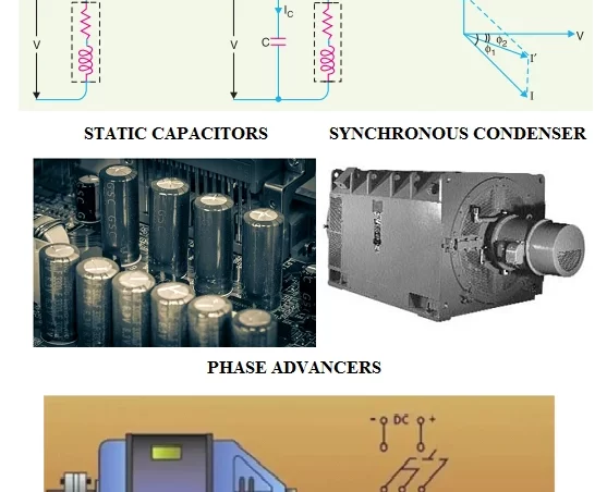
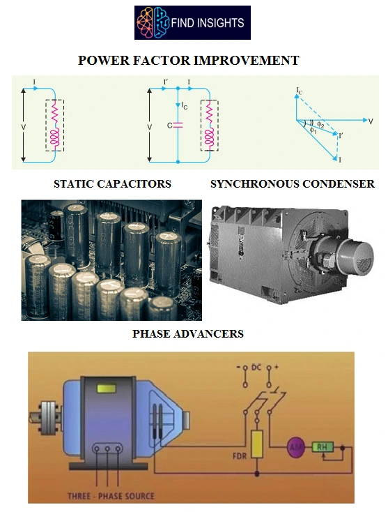
The power factor can be improved by connecting capacitors in parallel with the equipment operating at lagging power factor. The capacitor (generally known as static capacitor) draws a leading current and also partly or completely neutralises the lagging reactive component of load current. This raises the power factor of the load. For three-phase loads, the capacitors can be connected in delta or star as shown in Figure. Static capacitors are invariably used for power factor improvement in factories. It is widely used method of power factor improvement.
Advantages
- They have low losses.
- They require little maintenance as there are no rotating parts.
- They can be easily installed as they are light and require no foundation.
- They can work under ordinary atmospheric conditions.
Disadvantages
- They have short service life ranging from 8 to 10 years.
- They are easily damaged if the voltage exceeds the rated value.
- Once the capacitors are damaged, their repair is uneconomical.
Power Factor Improvement Method by using Synchronous Condenser

- A synchronous motor takes a leading current when over-excited and, therefore, behaves as a capacitor. An over-excited synchronous motor running on no load is known as synchronous condenser. When such a machine is connected in parallel with the supply, it takes a leading current which partly neutralises the lagging reactive component of the load. Thus the power factor is improved.
- Figure shows the power factor improvement by synchronous condenser method. The 3φ load takes current IL at low lagging power factor cos φL. The synchronous condenser takes a current Im which leads the voltage by an angle φm*. The resultant current I is the phasor sum of Im and IL and lags behind the voltage by an angle φ. It is clear that φ is less than φL so that cos φ is greater than cos φL. Thus the power factor is increased from cos φL to cos φ. Synchronous condensers are generally used at major bulk supply substations for power factor improvement. It is one of the important method of power factor improvement
Advantages
- By varying the field excitation, the magnitude of current drawn by the motor can be changed by any amount. This helps in achieving stepless control of power factor
- The motor windings have high thermal stability to short circuit currents.
- The faults can be removed easily.
Disadvantages
- There are considerable losses in the motor.
- The maintenance cost is high.
- It produces noise.
- Except in sizes above 500 kVA, the cost is greater than that of static capacitors of the same rating.
- As a synchronous motor has no self-starting torque, therefore, an auxiliary equipment has to be provided for this purpose.
Power Factor Improvement Method by using Phase Advancers

Phase advancers are used to improve the power factor of induction motors. The low power factor of an induction motor is due to the fact that its stator winding draws exciting current which lags behind the supply voltage by 90o If the exciting ampere turns can be provided from some other a.c. source, then the stator winding will be relieved of exciting current and also the power factor of the motor can be improved. This job is accomplished by the phase advancer which is simply an a.c. exciter. The phase advancer is mounted on the same shaft as the main motor and also is connected in the rotor circuit of the motor. It provides exciting ampere turns to the rotor circuit at slip frequency. By providing more ampere turns than required, the induction motor can be made to operate on leading power factor like an over-excited synchronous motor.
Advantages:
Phase advancers have two principal advantages.
- Firstly, as the exciting ampere turns are supplied at slip frequency, therefore, lagging kVAR drawn by the motor are considerably reduced.
- Secondly, phase advancer can be conveniently used where the use of synchronous motors is unadmissible.
Disadvantages
- However, the major disadvantage of phase advancers is that they are not economical for motors below 200 H.P
POWER FACTOR FAQ
How power factor is improved?
Power factor can be improved by the following method
- Static Capacitors
- Synchronous Condenser
- Phase Advancers
Which device is used for power factor improvement?
Static Capacitors. The power factor can be improved by connecting capacitors in parallel with the equipment operating at lagging power factor.
What is meant by power factor?
The cosine of angle between voltage and current in an a.c. circuit is known as power factor. In an a.c. circuit, there is generally a phase difference φ between voltage and current. The term cos φ is called the power factor of the circuit.
What is the power factor formula?
Power factor is measured using the formula Power Factor = cosɸ. where ɸ is the phase difference between the voltage and current phasor.
LIKE WHAT YOU’RE READING?
CHECK OUT SOME OF OUR OTHER GREAT CONTENT HERE:
- LVDT- CONSTRUCTION, WORKING PRINCIPLE , APPLICATIONS, ADVANTAGES, AND DISADVANTAGES
- HOW AN IGBT WORKS?
- SCR VI CHARACTERISTICS EXPLAINED IN DETAIL
- STEP UP TRANSFORMER: DEFINITION, CONSTRUCTION, WORKING & APPLICATIONS
- LIMITATIONS OF OHM’S LAW
- INDUCTION MOTOR: WORKING PRINCIPLE, TYPES & APPLICATION
- STRAIN GAUGE WORKING PRINCIPLE
- TYPES OF LIGHTNING ARRESTER
- WHAT IS OPERATING SYSTEM AND ITS TYPE
- WHAT ARE THE USES OF CAPACITOR
- WORKING PRINCIPLE OF SYNCHRONOUS MOTOR
- SYNCHRONOUS MOTOR STARTING METHOD
- WHY THE SYNCHRONOUS MOTOR IS NOT SELF STARTING
- WHAT IS A UNIVERSAL MOTOR ?


3 Comments